The ones I'm using have a response time down around the 3.5ns range.
On the front plate of the box I have drilled a hole that lines up with the photodiode that is just floating inside the enclosure. At the back we have a BNC and power jack.
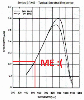
The internals are quite simple. The two images below are from a concise and good OSI datasheet.
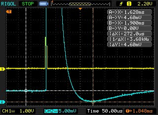
I constructed the coax cable as described with the two protection diodes at the scope end. Powered from my bench supply at Vbias=25V. The yellow trace is the square pulse (short little blip) from my PWM driver about 8us that triggers the laser with the hot end pointing directly at the detector - the blue trace.
The first time I built this I used Rs=10Gohm and C1=68pF
On the left of the detector trace we can see the ground voltage that is a result of the dark current that comes about when these things are reversed biased. The main thing I'm checking here is that for a given PWM period the detector is able to recover fully prior to the next pulse.
Just because I like making life hard for myself my laser is 523nm that is not so close to the peek sensitivity of the BPX65. If you do a parametric search at your favorite electronics shop you'll find that most of the devices available are for 900nm and above. Devices at my wavelength were either cheap and slow or very expensive and did not quote response times?
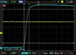
Anyway once I was all setup this is what I found, the best rise time I cold muster was 168ns.
In this configuration the peek voltage (about 372mV in my case) depends on the amount of light that falls on the detector, that in turn seems to have a serious effect on the rise-time. It does not matter how wide your PWM pulse width is because that is never going to change the instantaneous energy the photodiode sees.
Next I reduced the resistor such that Rs=1Mohm and C1=68pF, and dispite the overshoot I was getting 60ns.
This could be improve upon to 50ns by putting a lense in front to focus the beam at the detector junction.
I ruled out the coax being at fault by connecting the standard scope probe and got a nearly identical waveform. So that leaves the following variables I need to workout.
Depending on what rule we use my 100MHz scope should be able to give a 0.35/100MHz= 3.5ns rise time so the two unknowns here are the detector itself and the laser. Currently I have no way of knowing the rise time of the laser so might look at a toothed wheel setup rather then the PWM and see what difference that makes.
I will also get a red laser and see it the photodiode response time is affected by wavelength.
I have a few of these photodiodes on hand so will be building new detectors with them - Marktech MTD5010W


No comments:
Post a Comment